Pockets & tool access
Give the cutting edge room to reach, clear chips and leave the required corner.
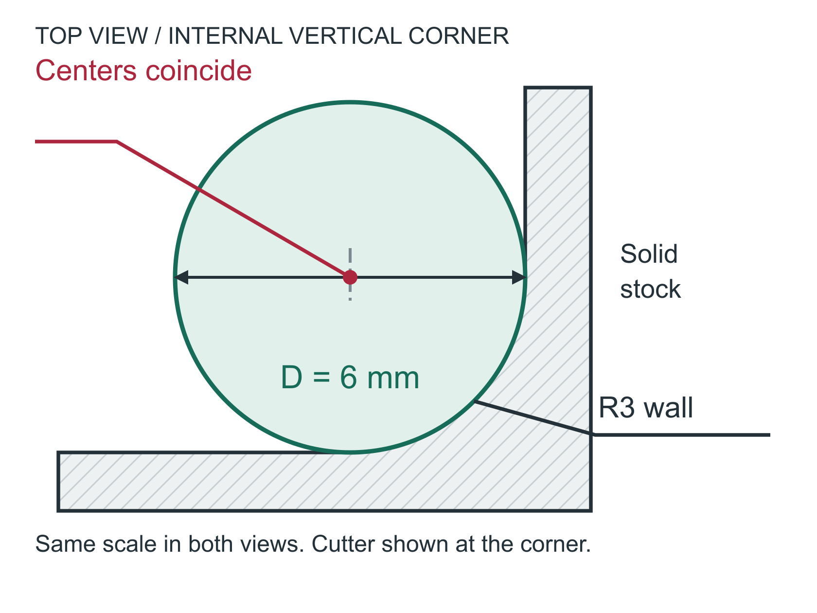
R3 corner / diameter 6 cutter
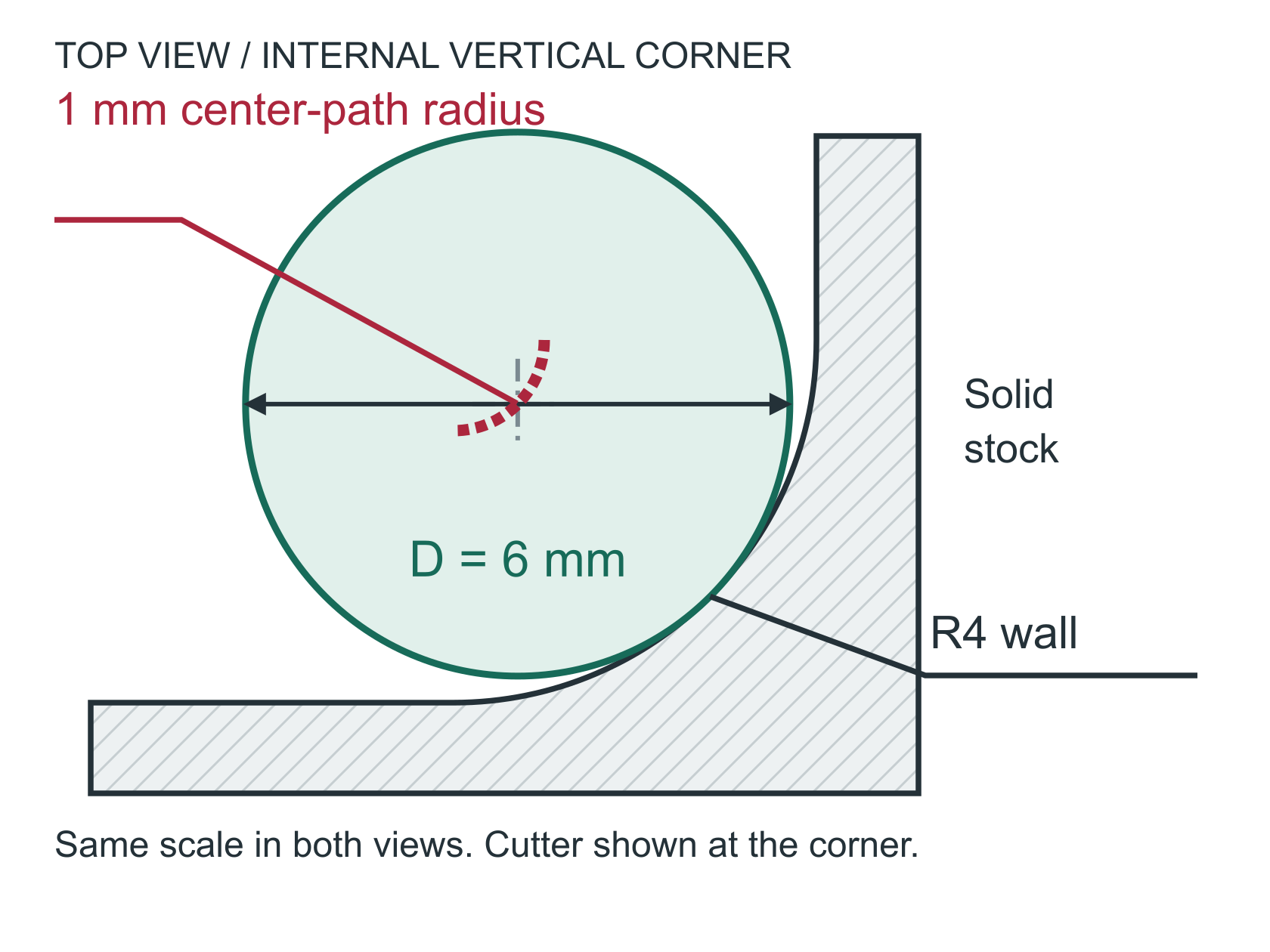
R4 corner / diameter 6 cutter
Corner-path radius = R - D/2
R3: 3 - 6/2 = 0 mm | R4: 4 - 6/2 = 1 mm03Reduce unnecessary reach
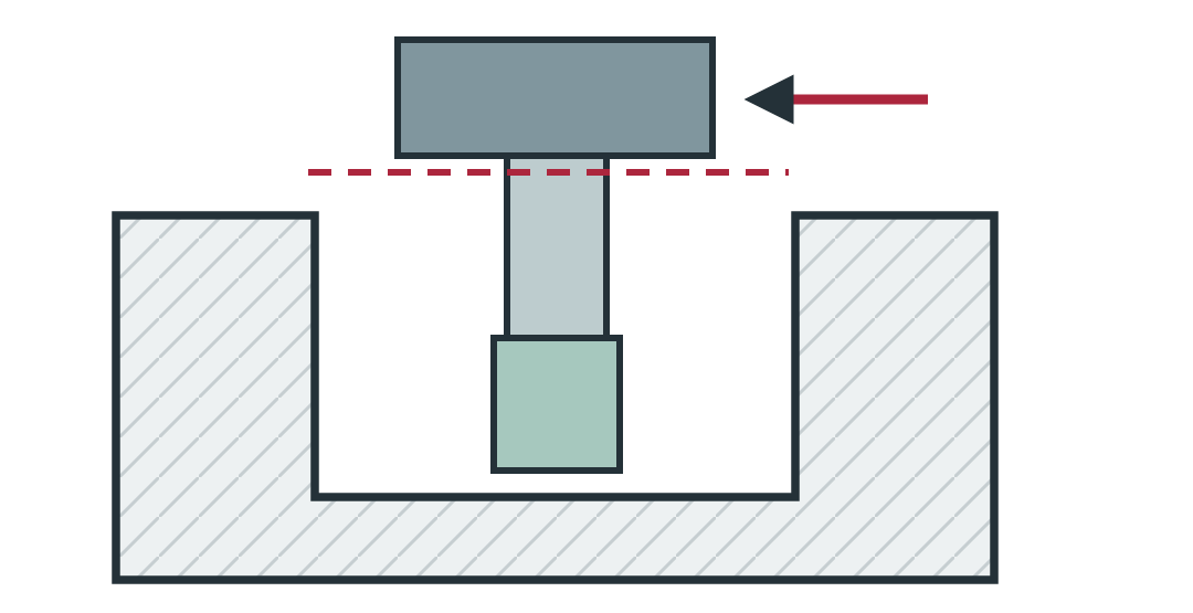
Flutes provide chip space; the neck and holder also need clearance. A deep pocket may require a long, less rigid tool.
CAD: keep nonfunctional pockets shallow.
04Clear square mating corners
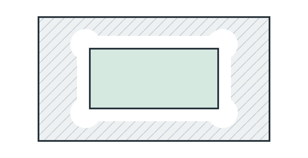
A round tool leaves an inside radius. Local corner relief can clear a square insert; verify fit and the remaining load-bearing section.
CAD: add relief only where permitted.
05Plan the tool approaches
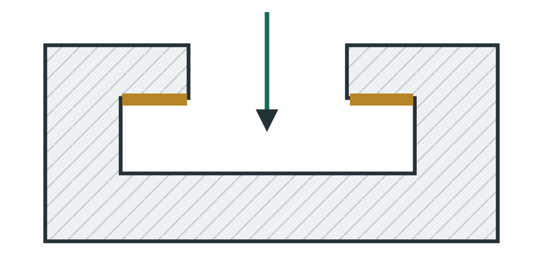
Group accessible features where function permits. Re-clamping adds handling; undercuts still need a tool entry and exit path.
CAD: review access and necessary setups early.
06Distinguish blind and through
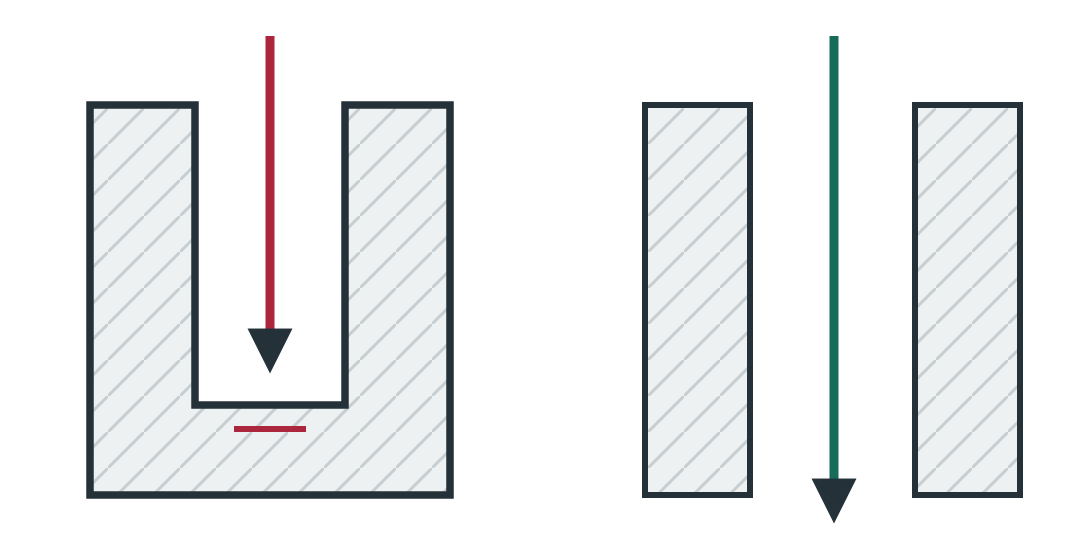
Wire EDM needs a through path in conductive material and wire entry. A blind floor needs another approach, such as sinker EDM.
CAD: preserve required floors and sealing walls.
A larger corner helps the toolpath; it does not prove tool reach. Check flute, neck and holder clearance separately.
BEFORE RELEASE Protect fit, loads, sealing and required material sections when changing geometry.
- Identify the smallest internal vertical radius.
- Dimension pocket depth separately from wall height.
- Check tool and holder access to every feature.
- Identify square-corner mating requirements.
- Mark any permitted corner relief on the drawing.
- Discuss inaccessible undercuts before release.