Thin walls & material behavior
Review the whole wall: height, thickness, support and material condition.
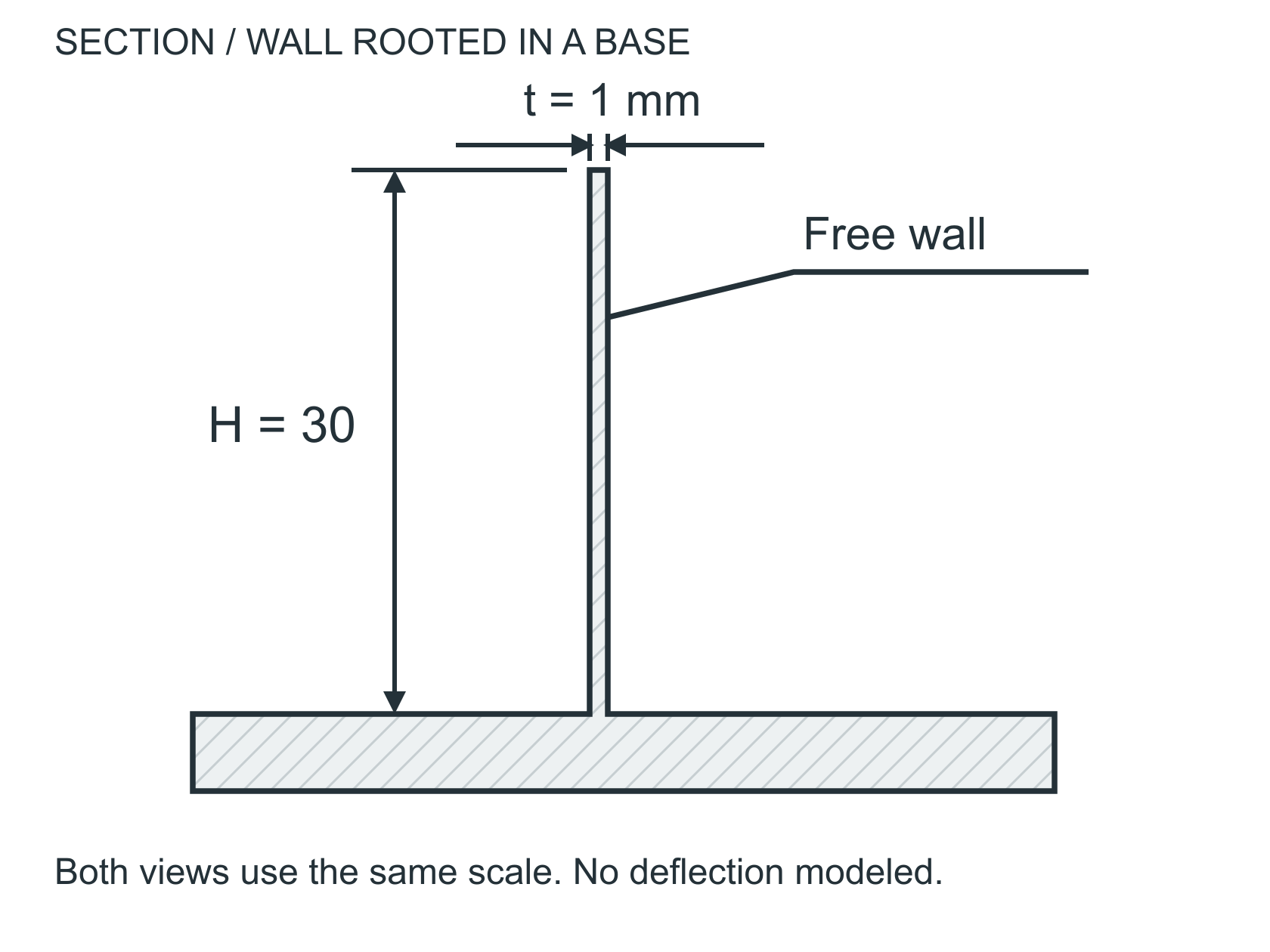
H = 30 mm / t = 1 mm
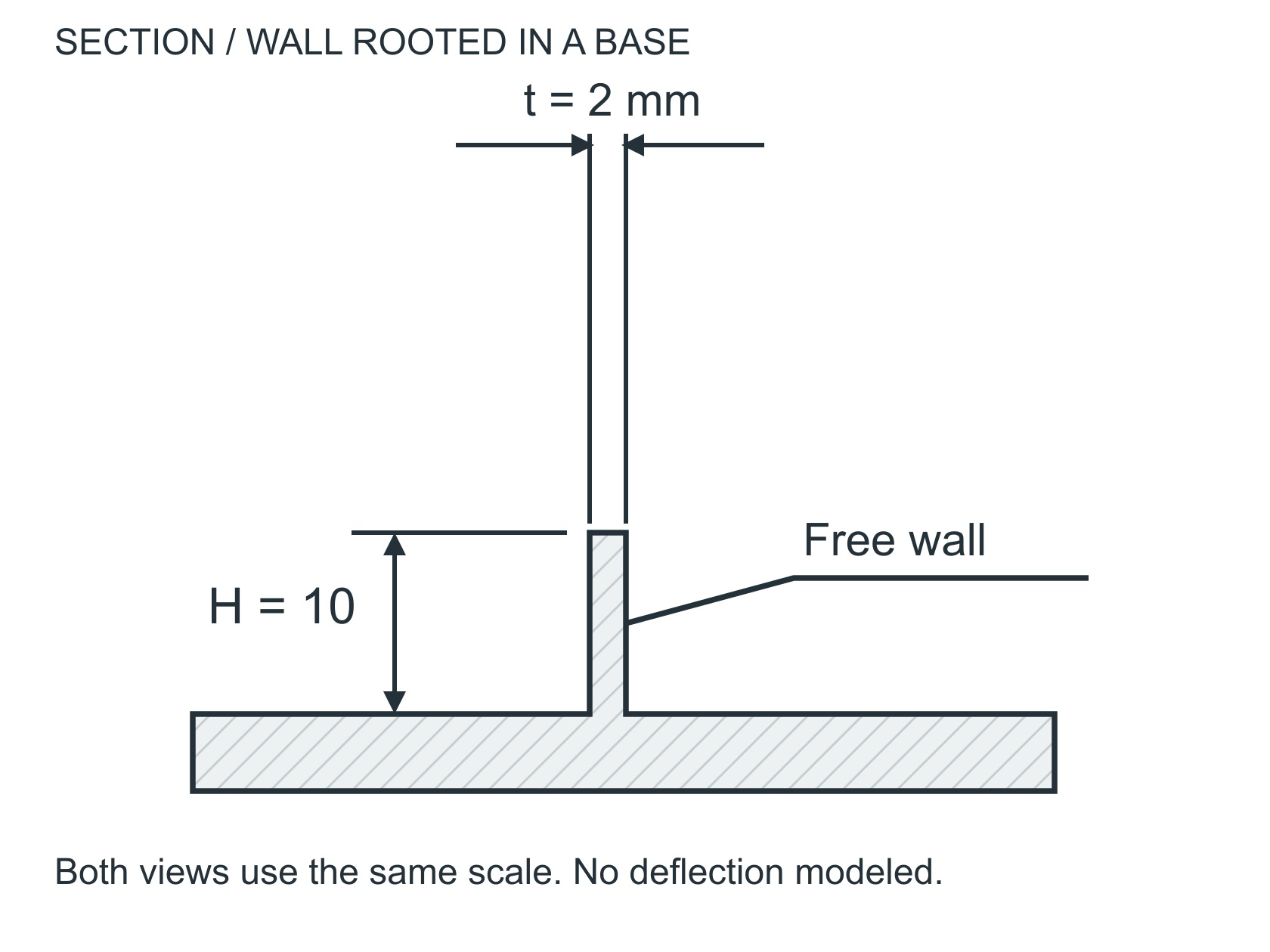
H = 10 mm / t = 2 mm
Geometry ratio = unsupported height / thickness
30 / 1 = 30 | 10 / 2 = 503Support the free span
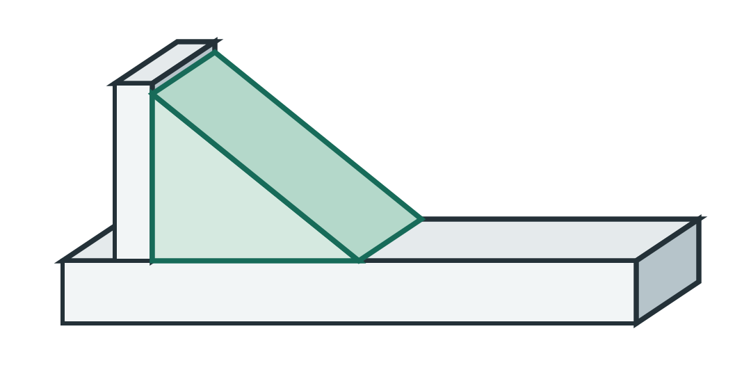
A rib or thicker root can help support a wall. Preserve clearance and mass targets; check loads, fatigue and stress concentrations.
CAD: shorten spans or add a permitted rib.
04Provide a stable grip
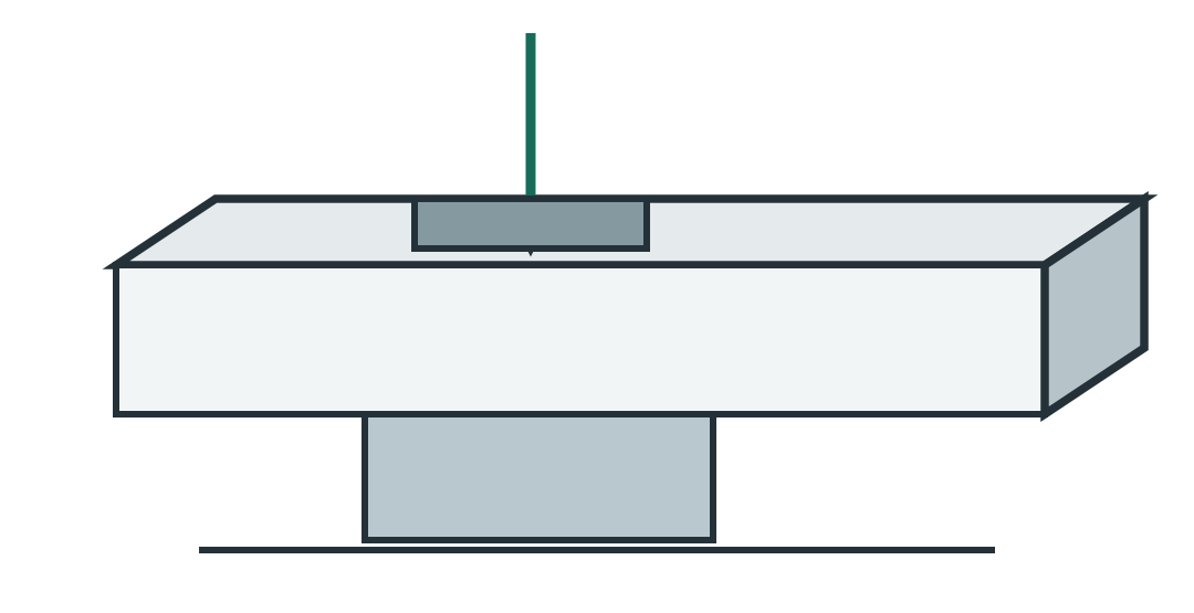
Thin features can move under clamp force and spring back when released. A supported gripping area helps the workholding plan.
CAD: leave accessible support and grip faces.
05Avoid needless one-sided cuts
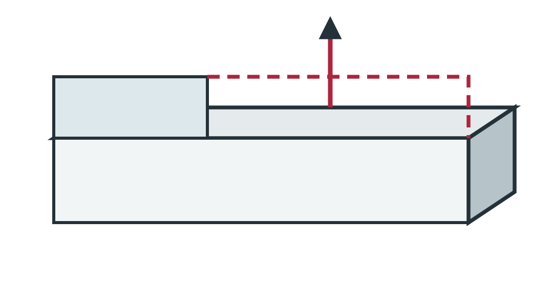
Residual stress and asymmetric removal can move the part. Review stock condition and the roughing/finishing sequence with the shop.
CAD: remove only the material function needs.
06Specify the material state
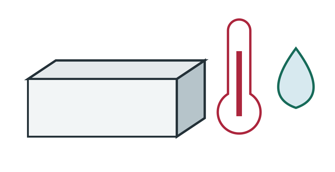
Alloy/temper and polymer grade matter. Temperature, moisture and stress relaxation can change dimensions after machining.
CAD: define grade and measurement condition.
H/t describes slenderness. It is not a stiffness calculation, a vibration prediction or a universal pass/fail limit.
BEFORE RELEASE Protect fit, loads, sealing and required material sections when changing geometry.
- Dimension height and thickness together.
- Show where supports or ribs are permitted.
- Identify critical free-state dimensions.
- Specify alloy, temper/hardness or polymer grade.
- Review stock stress and asymmetric removal.
- Agree measurement temperature and conditioning when relevant.