Tolerances & datums
Define the functional relationship, then agree how it will be made and measured.
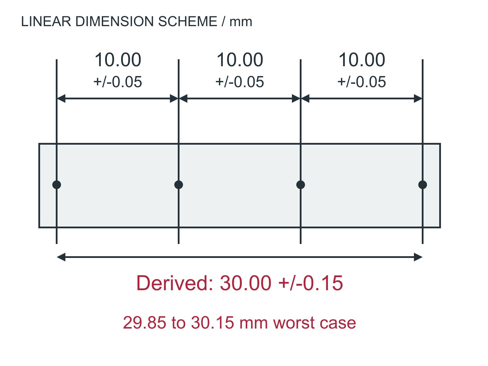
Worst-case overall variation: +/-0.15 mm
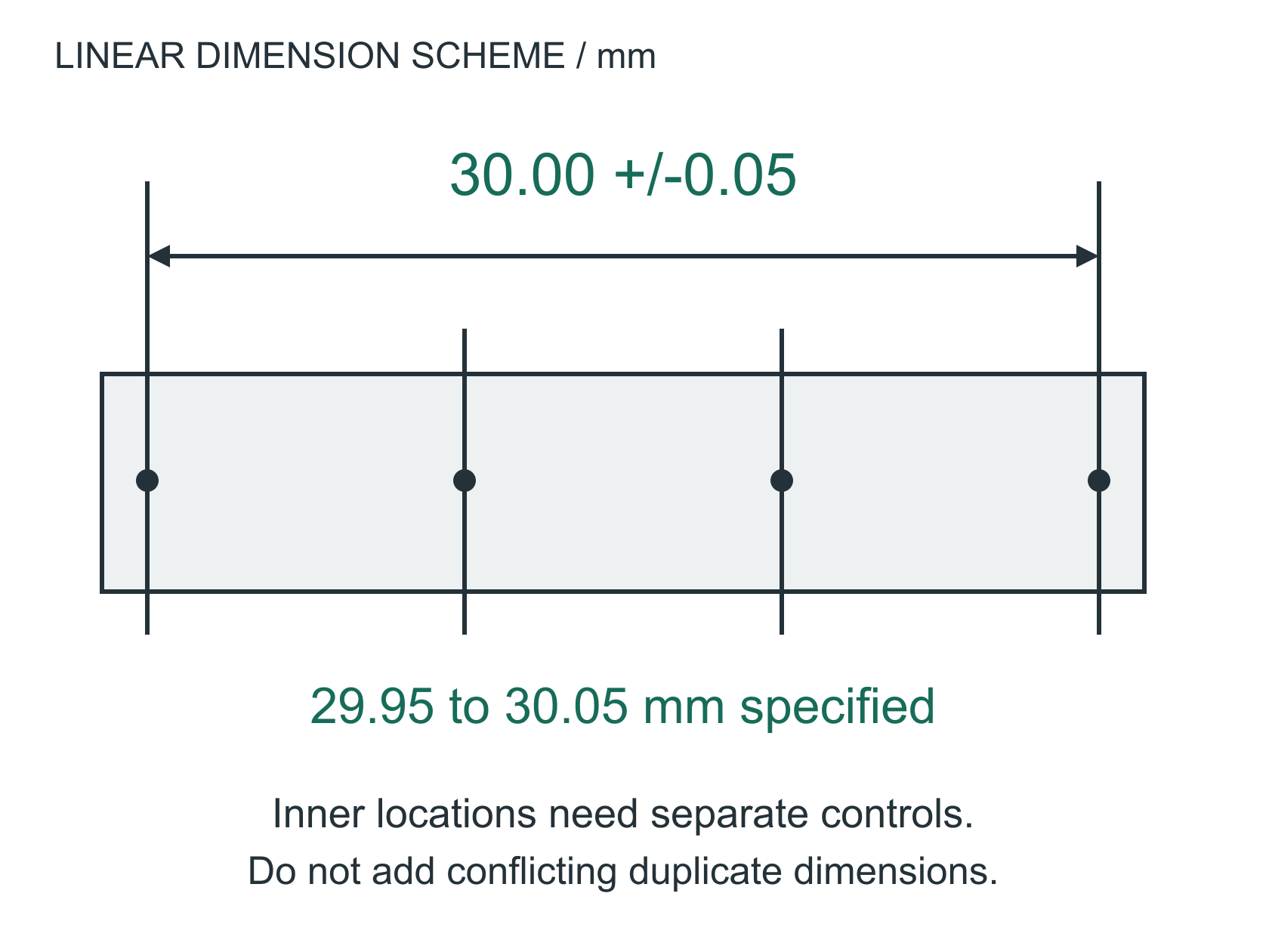
Specified overall variation: +/-0.05 mm
Worst-case chain: add absolute tolerance contributions
0.05 + 0.05 + 0.05 = +/-0.15 mm on the sum03Choose assembly references
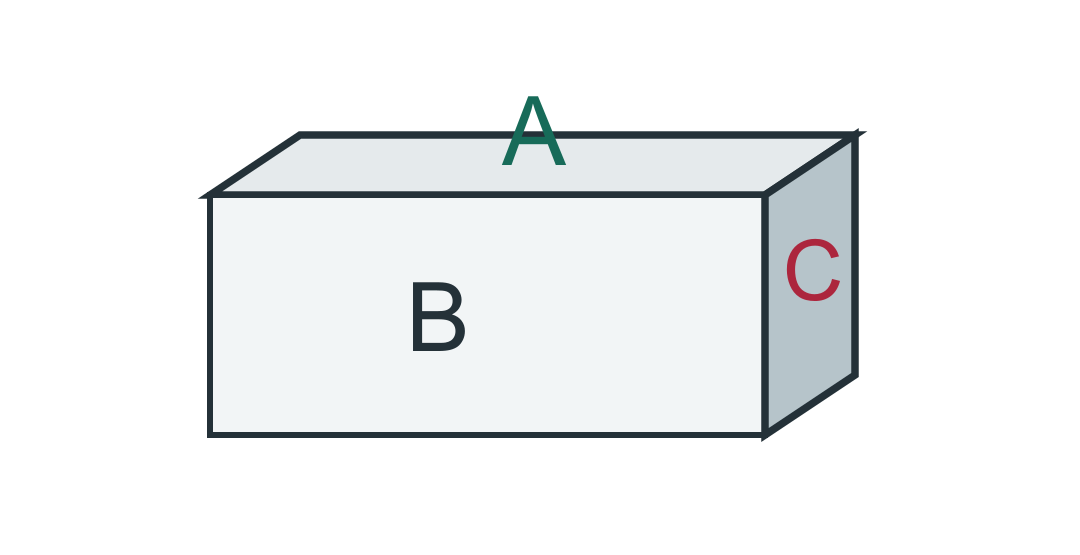
Datums are references for controlling geometry. Start with how the part seats, locates and clocks in its assembly.
CAD: select accessible functional datum features.
04Make the feature measurable
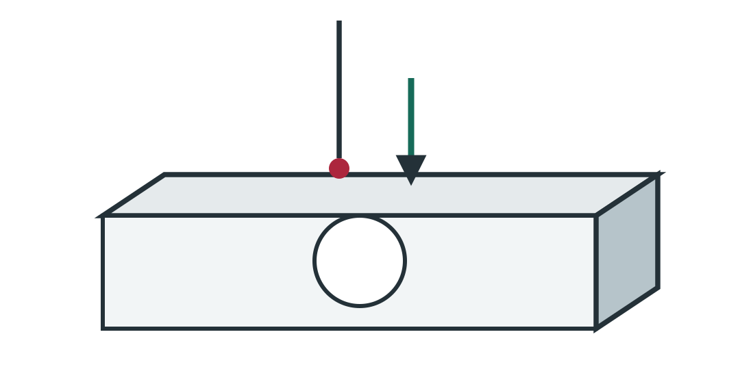
A probe or gauge needs access. Discuss critical features and inspection fixturing early; a tolerance needs a suitable measurement method.
CAD: leave access to the controlled feature.
05Put precision where it matters
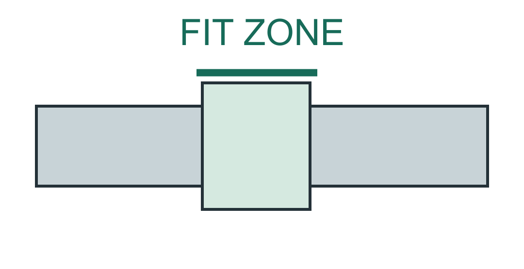
Identify sealing, sliding, bearing and alignment interfaces. Blanket tight tolerances add work without necessarily helping function.
CAD: apply tight controls locally where needed.
06Define when size must be met
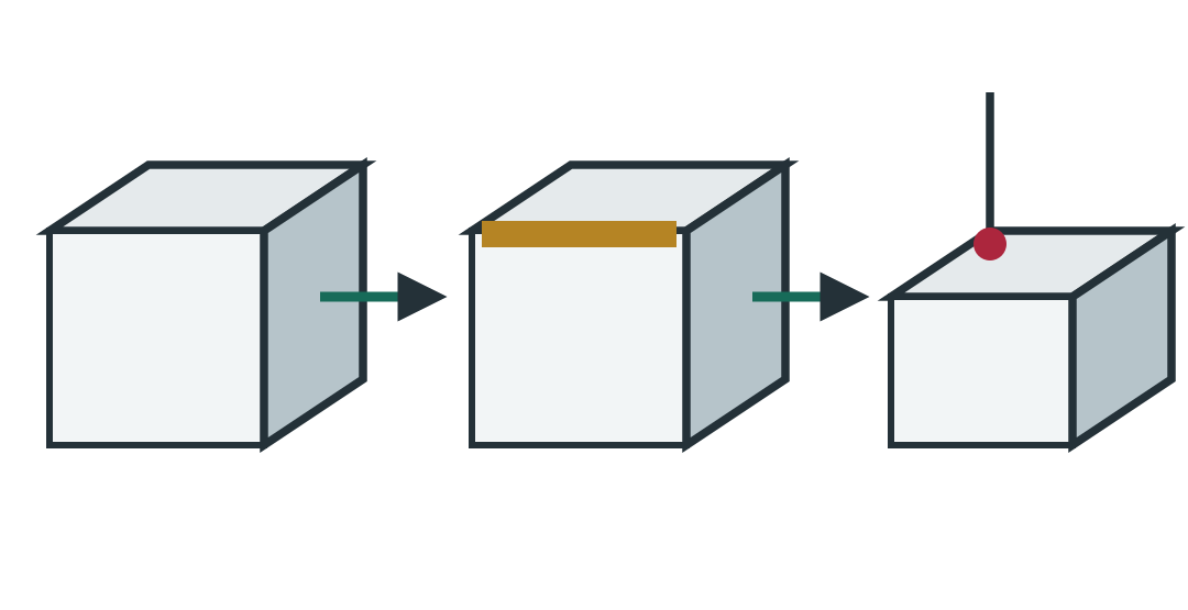
Coating, heat treatment and temperature can change size or form. The inspection condition belongs in the definition of the part.
CAD: state pre-process versus final dimensions.
Changing the dimension layout does not improve the process. The tighter direct span is a new requirement to manufacture and inspect.
BEFORE RELEASE Protect fit, loads, sealing and required material sections when changing geometry.
- Identify function-critical interfaces.
- Check the complete tolerance stack.
- Define and order required datum references.
- Avoid conflicting duplicate dimensions.
- Confirm access for the proposed inspection method.
- State final condition and applicable standard.