Small design decisions have a big impact on machining cost and lead time. A part that's designed with manufacturing in mind can be half the price of one that isn't — with no change in function. These guidelines come from decades of quoting and cutting real parts. Apply them early in your design process and you'll get better parts, faster, for less.

Internal Corner Radii

The single biggest DFM issue we see on drawings

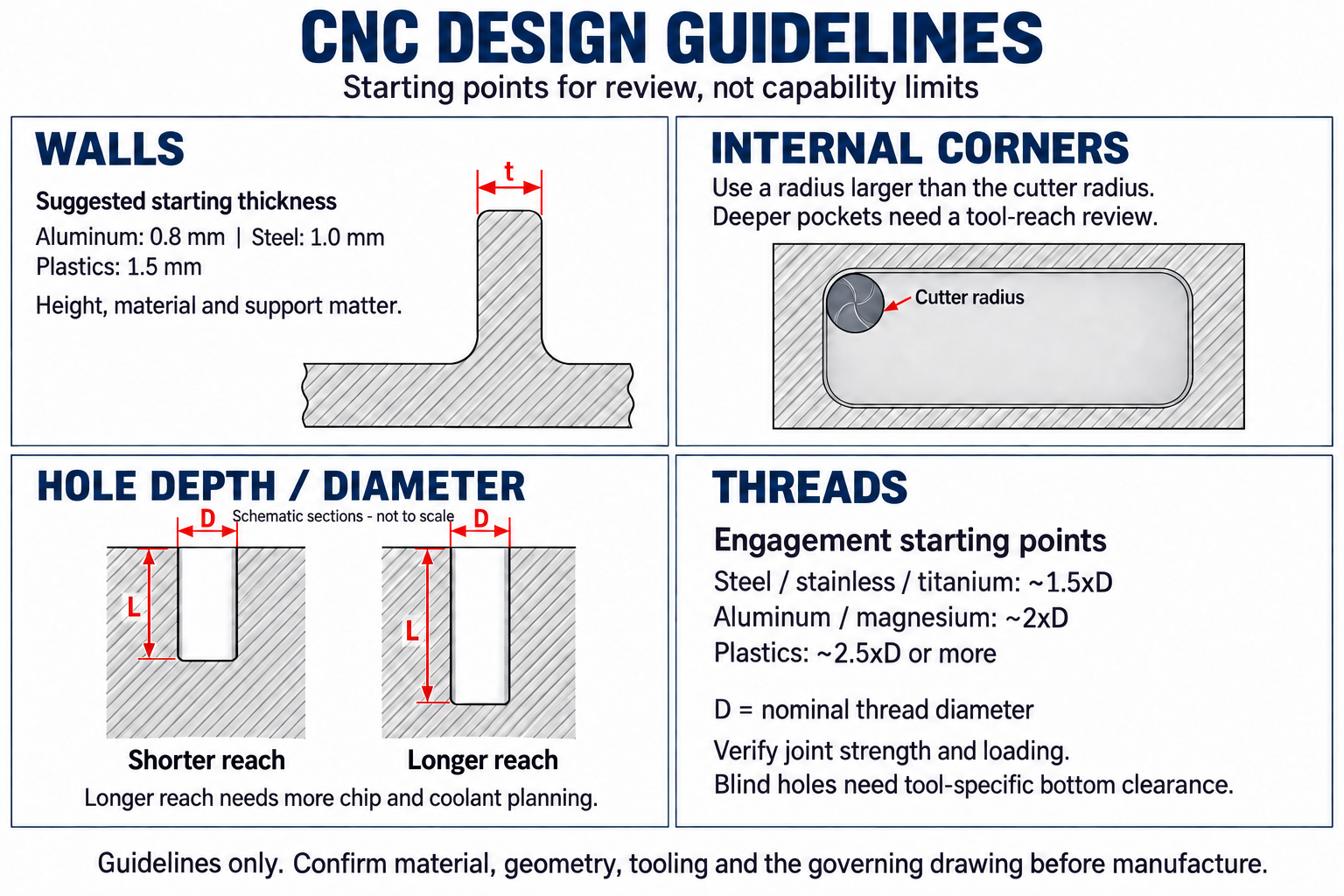
Do Design internal corners with a radius ≥ 1/3 the pocket depth

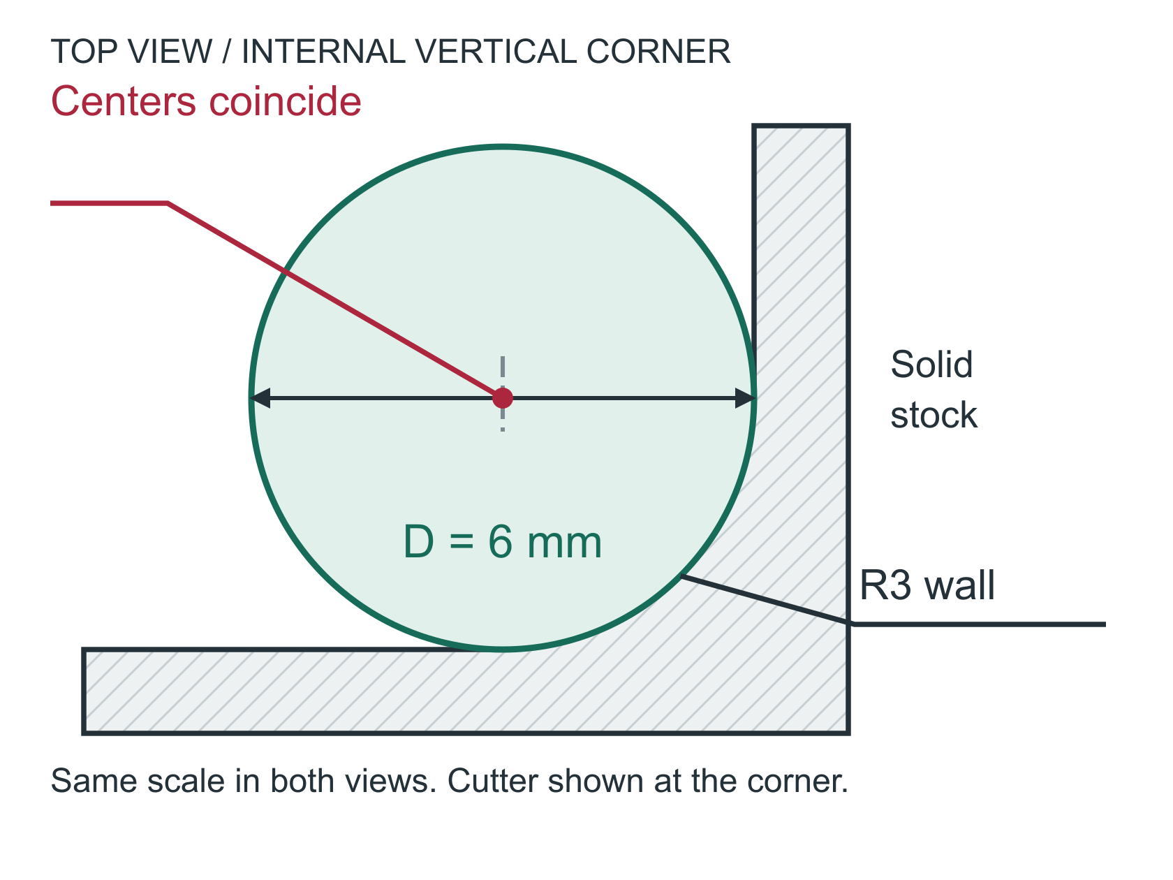
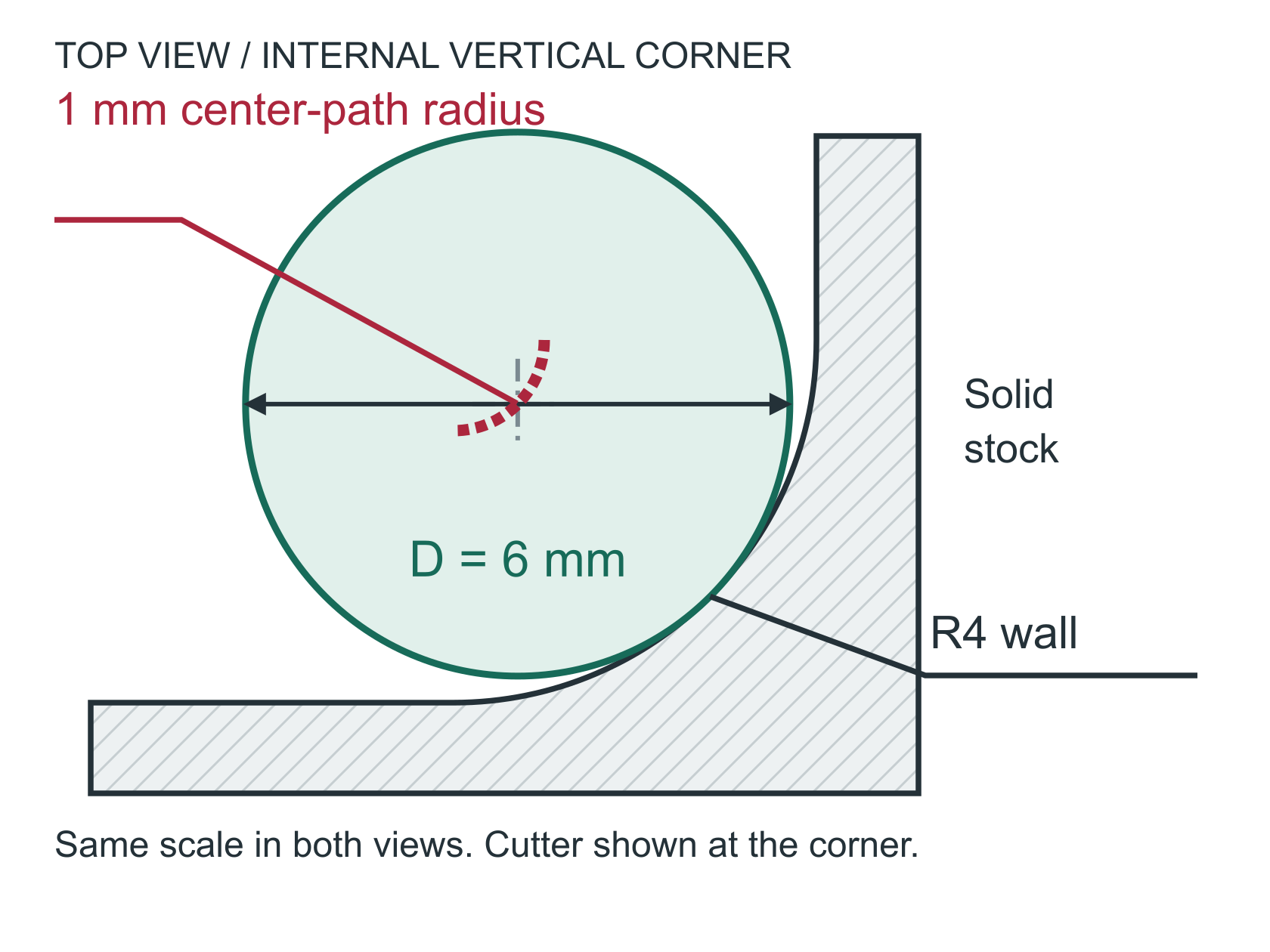
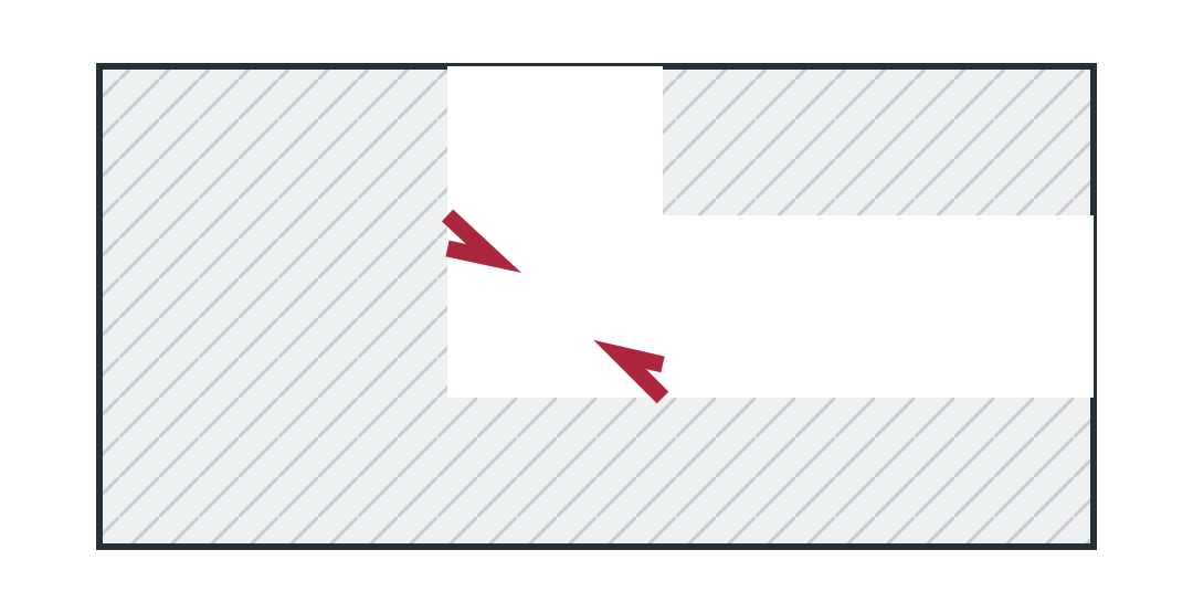
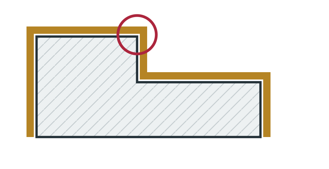
End mills are round — they physically can't cut a sharp 90° internal corner. Every internal pocket corner will have a radius equal to the tool radius. Designing with appropriate radii lets us use larger, more rigid tools that cut faster and last longer.

Standard Recommendation

  • Corner radius ≥ 1/3 of pocket depth
  • Example: 1.5" deep pocket → 0.500" radius minimum
  • Allows use of a 1" diameter end mill

If You Need Sharper Corners

  • We can go smaller, but smaller tools = slower feed rates = more time = more cost
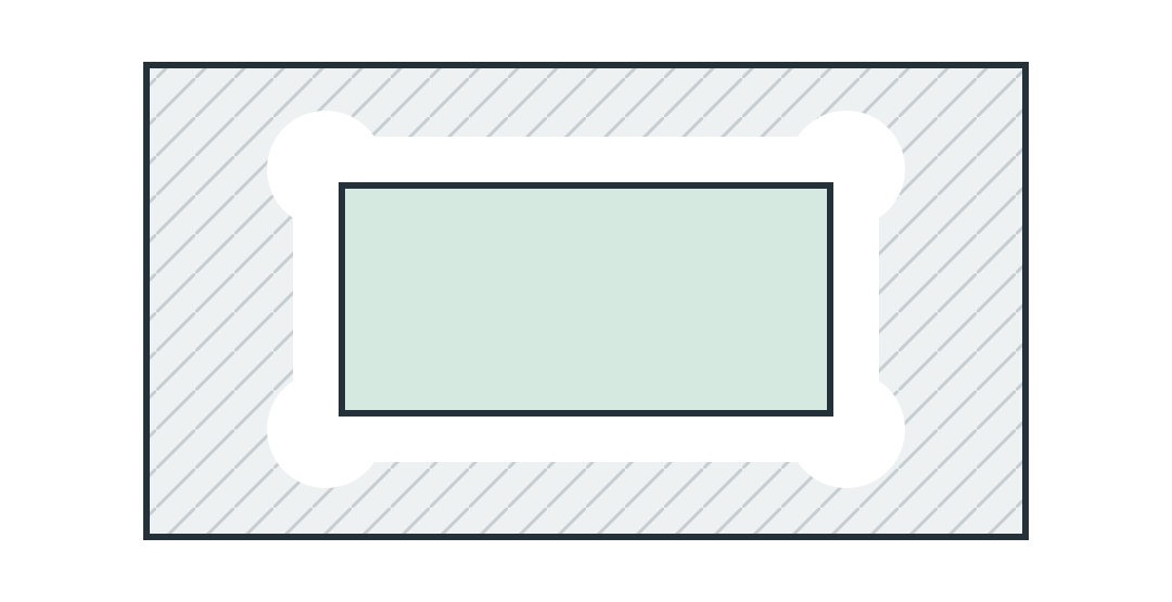
  • Dog-bone or T-bone relief cuts can give you functional sharp corners for mating parts
  • If a mating part needs to fit, consider radiusing the mating part's external corner instead

Wall Thickness

Do Keep walls thick enough to resist cutting forces

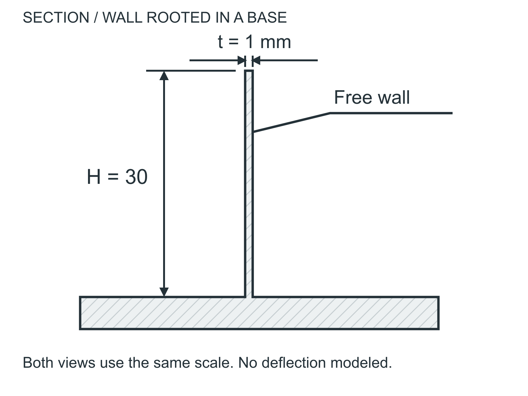
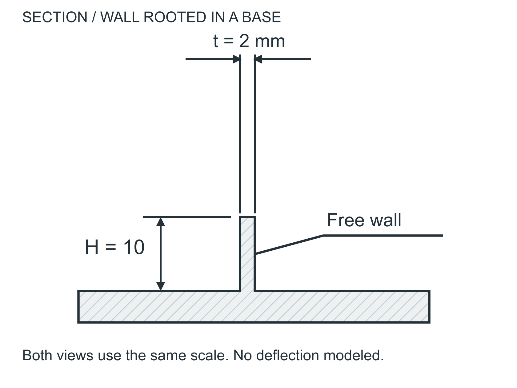
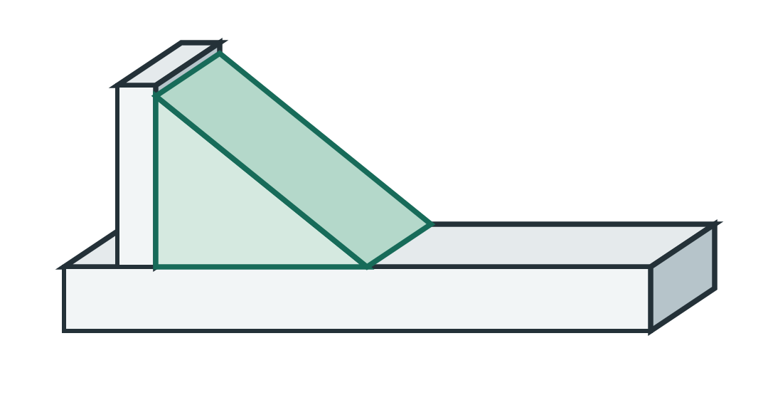
Thin walls deflect under cutting forces, causing chatter, poor surface finish, and out-of-tolerance dimensions. The thinner the wall relative to its height, the more problematic it becomes.

Minimum Wall Thickness

  • Aluminum: 0.040" (1mm) minimum, 0.060"+ preferred
  • Steel: 0.060" (1.5mm) minimum, 0.080"+ preferred
  • Plastics: 0.060" (1.5mm) minimum

Tall Thin Walls

  • Height-to-thickness ratio below 4:1 machines easily
  • 4:1 to 8:1 requires light passes and careful workholding
  • Above 8:1 gets expensive — consider alternate approaches

Holes & Bores

Do Use standard drill sizes and limit depth-to-diameter ratio

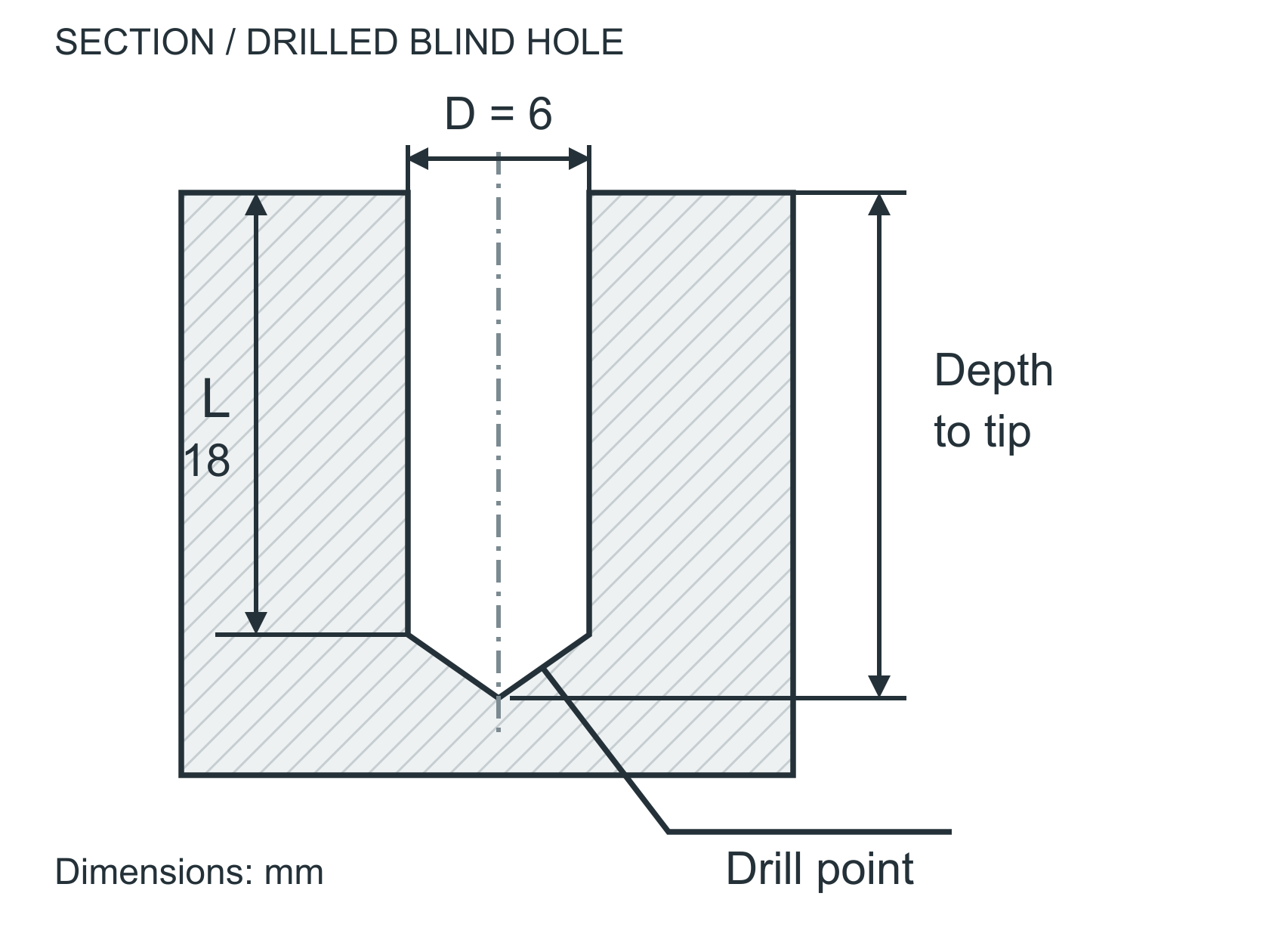
Hole Depth

  • Standard: Depth up to 4x diameter — easy, no issues
  • Deep: 4-10x diameter — requires peck drilling, slower
  • Very deep: Beyond 10x diameter — significantly more difficult, specialized tooling

Hole Best Practices

  • Use standard drill sizes (fractional, letter, or number) when possible
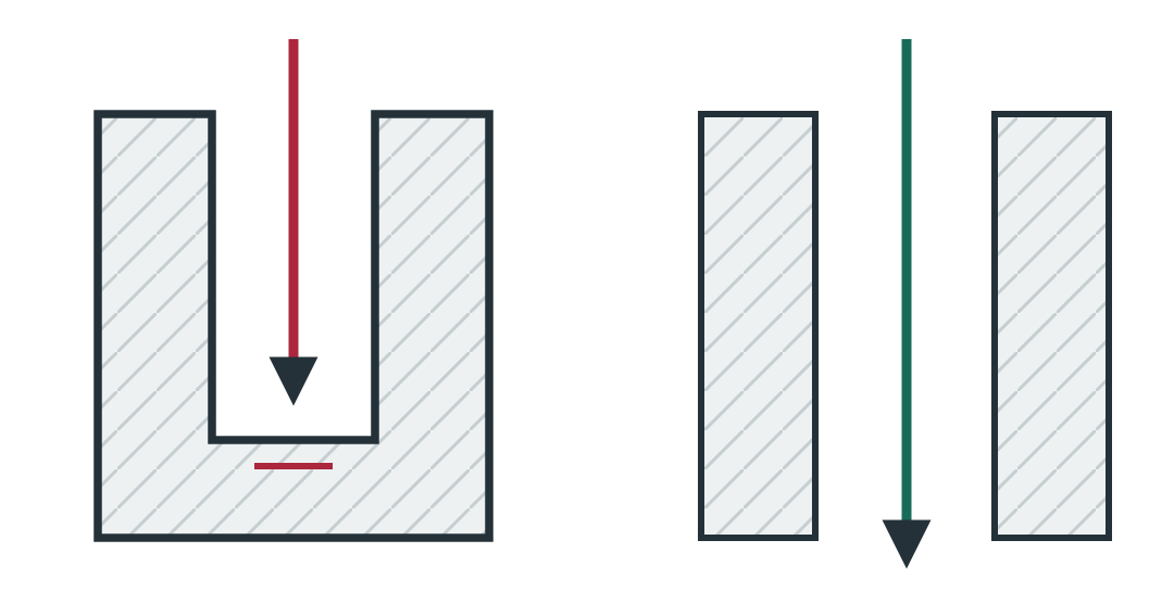
  • Flat-bottom holes cost more than through-holes — use through-holes when function allows
  • If you need a precise bore, spec the tolerance — a standard drill gives ~±0.003", reaming gives ~±0.0005"
  • Avoid holes on angled surfaces — drills wander on non-perpendicular entries

Threads

Do Use standard thread sizes and limit engagement depth

Thread Depth

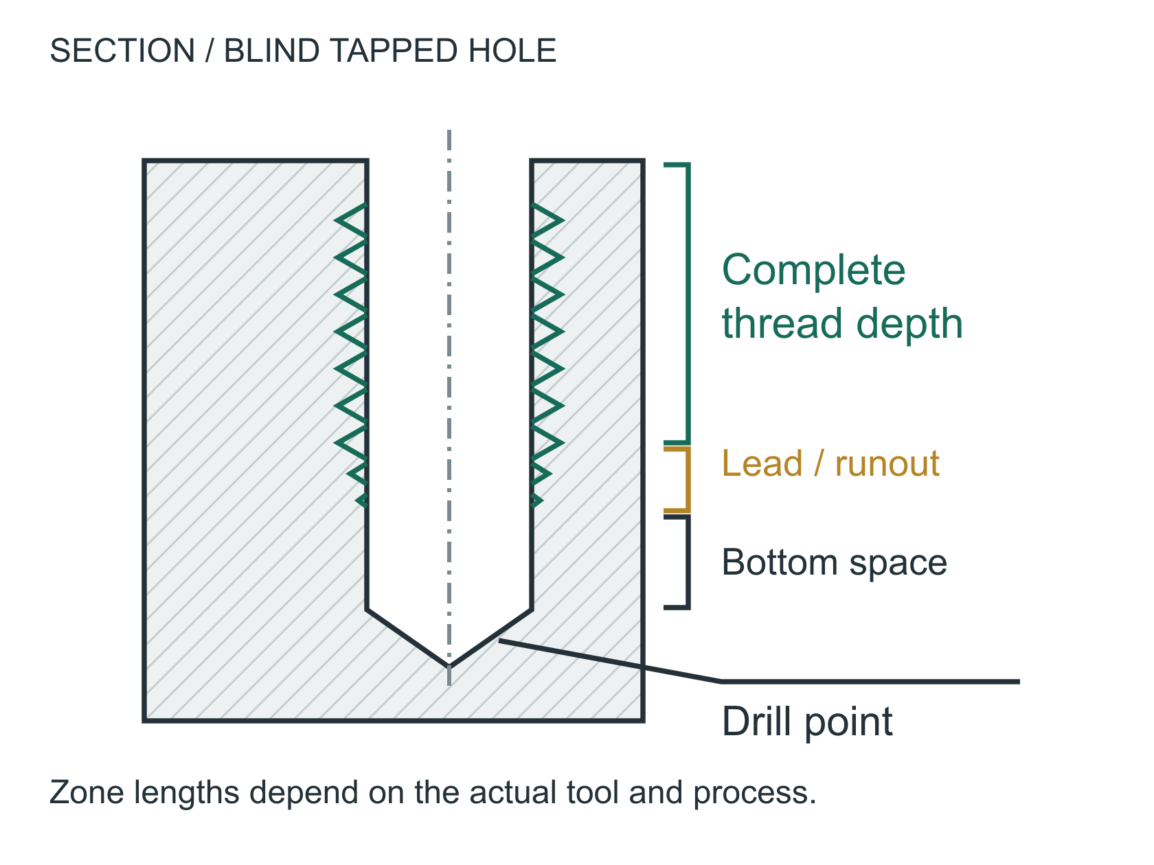
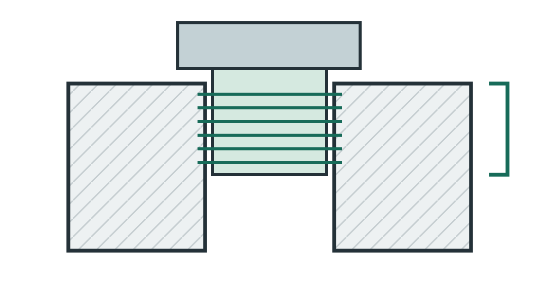
  • Rule of thumb: Thread engagement of 1.5x to 2x the bolt diameter provides full strength
  • Deeper than 2x adds cost without adding meaningful strength
  • In aluminum, use 2x diameter; in steel, 1.5x is sufficient

Thread Best Practices

  • Stick to standard UNC or UNF thread sizes
  • Spec thread class (2B is standard for most applications)
  • Add a chamfer or counterbore at the thread entry for easier assembly
  • If the tapped hole is blind, add at least 2 full thread pitches of clearance beyond the engagement depth
  • Consider Helicoil inserts for threads in aluminum that will see repeated assembly

Undercuts & Complex Features

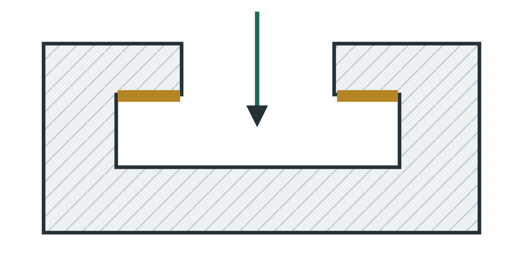
Avoid Features that can't be reached with standard tooling

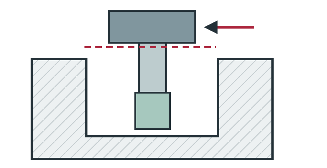
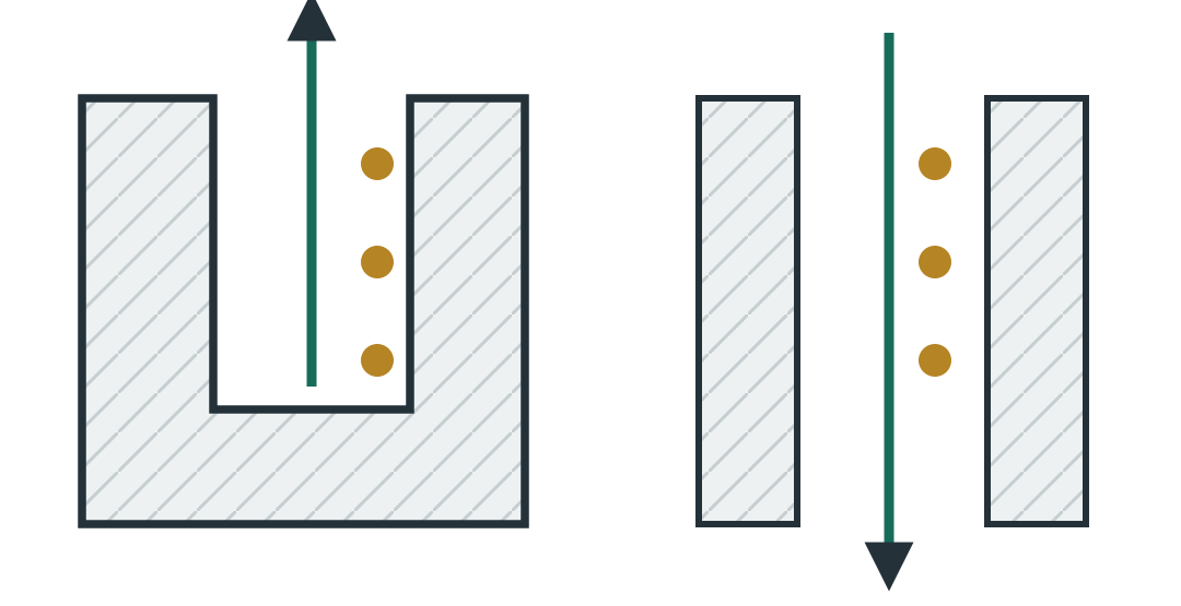
A CNC tool can only cut what it can physically reach. Internal undercuts, cavities with small openings, and features hidden behind other geometry add significant complexity.

Tips for Complex Parts

  • Can the part be split into two simpler pieces and assembled?
  • Can an undercut be eliminated by changing the mating part's geometry?
  • Internal features must be accessible from one of the 6 sides of the billet
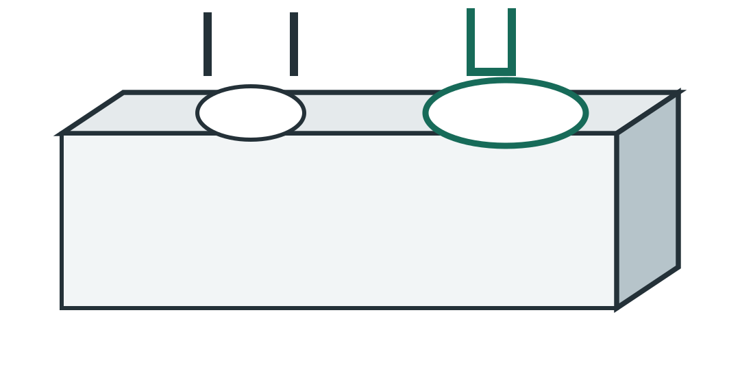
  • O-ring grooves and snap ring grooves are standard — we cut these daily
  • When in doubt, ask us. We'll tell you what's easy and what's expensive

Setups & Workholding

Do Design parts that can be clamped easily and machined in fewer setups

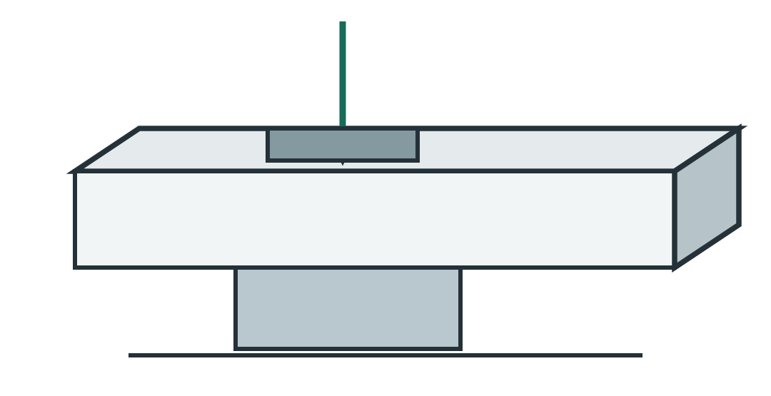
Every time we flip or re-fixture a part, it adds time and introduces alignment error. Parts that can be completed in fewer setups cost less and hold tighter tolerances between features.

Reduce Setups

  • Keep features on as few sides as possible — if all holes and pockets can be on one face, it's a one-setup part
  • Include flat clamping surfaces — give us something to grip. Odd shapes without a flat reference are harder to fixture
  • Consider vise-friendly geometry — two parallel sides at least 0.25" tall give us a solid grip
  • Our Kitamura horizontal machines 4 sides in one setup using a tombstone fixture — see our equipment

Surface Finish

Do Only specify surface finish where it functionally matters

Every surface has a finish — the question is whether you need to control it. Specifying a tight finish on a non-critical surface adds unnecessary time and cost.

When to Specify Finish

  • Sealing surfaces — O-ring grooves, gasket faces (32 Ra or better)
  • Bearing surfaces — shaft journals, bore fits (32-16 Ra)
  • Cosmetic / visible surfaces — customer-facing parts
  • Pre-anodize / pre-plate — surface finish affects final appearance

What to Expect by Default

  • Milling: 63-125 Ra with standard toolpaths
  • Turning: 32-63 Ra on OD/ID surfaces
  • Drilling: 125 Ra typical, reaming gets to 32 Ra
  • If no finish is called out, we machine to standard shop finish (~125 Ra)

Chamfers & Edge Breaks

Do Add chamfers to thread entries, mating edges, and handling surfaces

Best Practices

  • Thread entry chamfers: 45° x 0.015-0.030" — makes bolt start easier
  • Bore entries: chamfer for press-fit or bearing insertion
  • Sharp edges: add a general note "Break all sharp edges 0.005-0.015"" — this is faster than deburring to specific dimensions
  • Avoid specifying chamfers on internal pocket floors — the end mill already leaves a small radius

Cost Impact

  • A general "break sharp edges" note costs almost nothing — we do this as part of standard deburring
  • Specific chamfer dimensions (e.g., 0.030 x 45° ±0.005) on every edge adds time for setup and inspection
  • Only dimension chamfers that matter for function (thread starts, assembly fits)

Engraving & Part Marking

Do Use CNC-friendly fonts and practical depths

Guidelines

  • Font height: 0.100" minimum for legibility (0.150"+ preferred)
  • Depth: 0.010-0.020" is ideal — deep enough to read, shallow enough to cut fast
  • Font choice: Single-stroke/stick fonts are fastest. Filled (bold) fonts require pocket milling and take 5-10x longer
  • Location: Flat, accessible surfaces only — avoid engraving on curved or angled faces

Common Part Marking

  • Part numbers and revision letters
  • Serial numbers for traceability
  • Orientation marks (datum targets, "THIS SIDE UP")
  • Logo engraving — provide a DXF or vector file for best results

External Radii & Fillets

Do Add fillets to reduce stress concentrations and improve tool life

External Corners

  • Sharp external corners are easy to machine (tool naturally leaves a sharp edge)
  • External fillets and radii require a ball end mill or radius tool — slower but achievable
  • If you need a specific radius, call it out. Otherwise, we'll leave the edge sharp or break it per your general note

Floor Fillets

  • Where a vertical wall meets a pocket floor, there's always a radius (the tool's corner radius)
  • Specify a floor fillet that matches a standard tool radius: 0.015", 0.031", 0.062", 0.125"
  • Calling out R0.000 (sharp) on a floor fillet is physically impossible — we'll need to discuss alternatives

Material Selection for Manufacturability

Do Choose materials that balance performance with machinability

The material you choose directly impacts machining time, tool wear, and achievable tolerances. A material swap can sometimes cut your part cost in half with no change in function.

Easy Wins

  • 303 vs 304 stainless: If you don't need to weld it, 303 machines 40% faster
  • 6061 vs 7075 aluminum: 6061 is cheaper, easier to anodize, and strong enough for most applications
  • Delrin vs Nylon: Delrin holds tighter tolerances because it doesn't absorb moisture
  • C360 brass: Machines faster than anything else — ideal for fittings and connectors

Cost Multipliers

  • Titanium: Expect 3-5x the machining time of aluminum
  • Inconel / Hastelloy: 5-10x machining time, rapid tool wear, specialized tooling
  • Hardened steel (>40 HRC): Must use carbide tooling at reduced speeds
  • PEEK: Raw material is $50-100+/lb — minimize stock removal

See our full Materials Guide for properties and recommendations →

Prototype vs. Production Design

Do Tell us whether it's a prototype or production run — the approach changes

Prototypes (1-10 pcs)

  • We optimize for speed, not cycle time — get you parts fast for testing
  • Consider relaxing non-critical tolerances to reduce turnaround
  • We can machine from oversized stock to avoid material lead times
  • Don't over-engineer the drawing — functional prototypes don't need inspection reports on every dimension
  • Design changes are cheap at this stage — iterate now, not later

Production (50+ pcs)

  • We optimize toolpaths and fixturing for minimum cycle time per part
  • Custom fixtures and workholding pay for themselves at volume
  • Material choice matters more — free-machining grades save significant time at scale
  • Consistent stock sizes reduce setup time between batches
  • First article inspection and documentation up front prevent issues on the run

Common DFM Mistakes We See

Issues that come up frequently on customer drawings

Over-Tolerancing Everything

Putting ±0.001" on every dimension when only 3 features actually need it. This doubles machining time and inspection cost for no functional benefit.

Sharp Internal Corners

Designing square internal pockets expecting sharp 90° corners. End mills are round — there's always a radius. Design your mating part to accommodate it.

Deep Narrow Slots

A 0.060" wide slot that's 1.5" deep requires a long, thin end mill that deflects and breaks. Widen the slot or reduce depth if function allows.

No Datum References

Tolerancing features without specifying which surfaces are datums. We need to know what to set up from — otherwise we're guessing at your intent.

Unnecessary Cosmetic Specs

Calling out 16 Ra finish on a hidden surface that bolts to another part. Save the fine finish call for surfaces that seal, slide, or show.

Ignoring Stock Sizes

Designing a 2.030" wide part that forces us to buy 2.5" or 3" stock. A 1.990" width machines from 2" flat bar — saving material cost and one facing operation.

Missing Dimensions

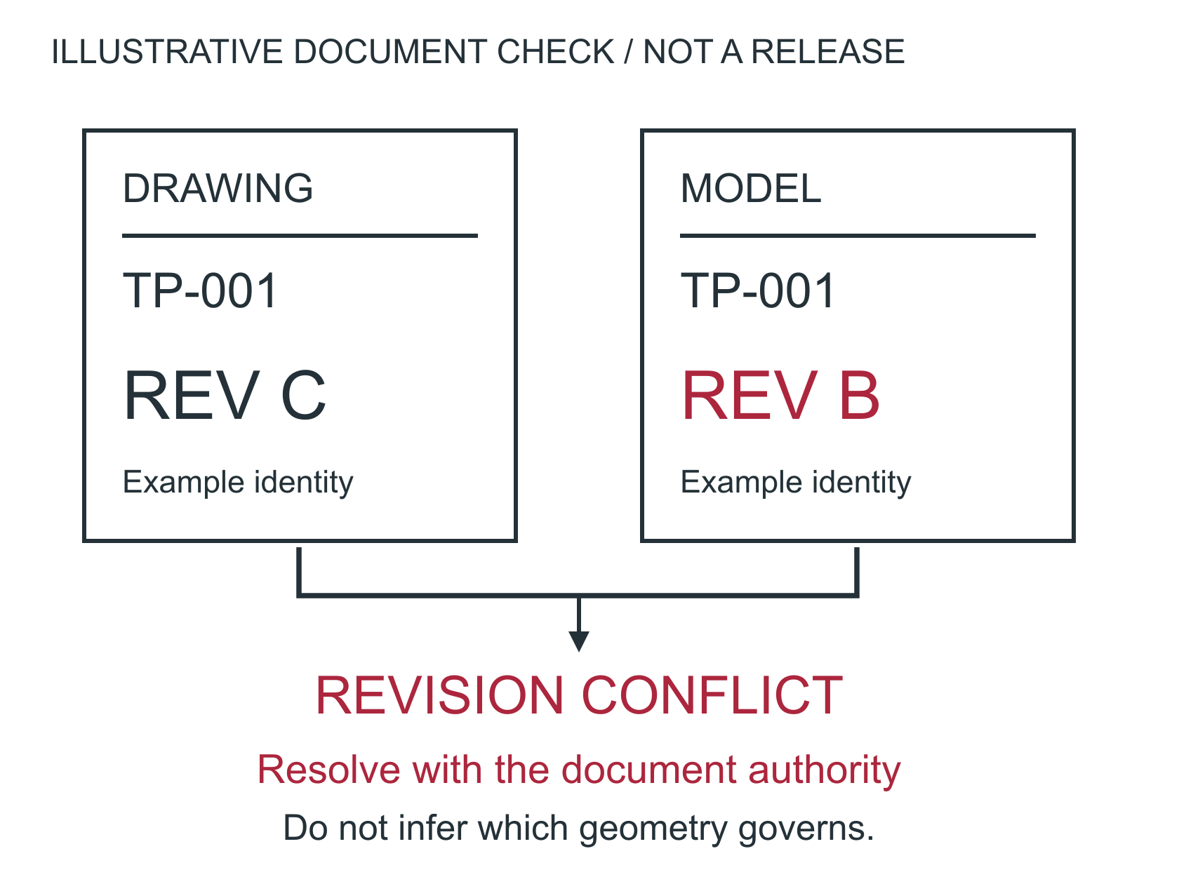
Sending a 3D model with no drawing, or a drawing missing critical dimensions. We need explicit tolerances on features that matter — a model alone doesn't tell us what's critical.

Thin Floors in Deep Pockets

A 2" deep pocket with a 0.030" floor deflects and can punch through. If you need a thin floor, reduce pocket depth or add ribs for support.
Preparing Your Drawing for Quoting

A clear drawing gets you a faster, more accurate quote

Include All Dimensions

Don't make us guess. Every feature should be dimensioned. Missing dimensions delay quoting while we ask for clarification.

Specify Material & Condition

Not just "aluminum" — which alloy and temper? "6061-T6" vs "7075-T6" makes a big difference in price and capability.

Note Surface Finish Requirements

If specific surfaces need a particular Ra value, call it out. If anodizing, plating, or coating is needed, note that too.

Include Quantity

Per-part price varies significantly with quantity. Give us the quantity (or range) so we can quote the most efficient process.

Include a Title Block

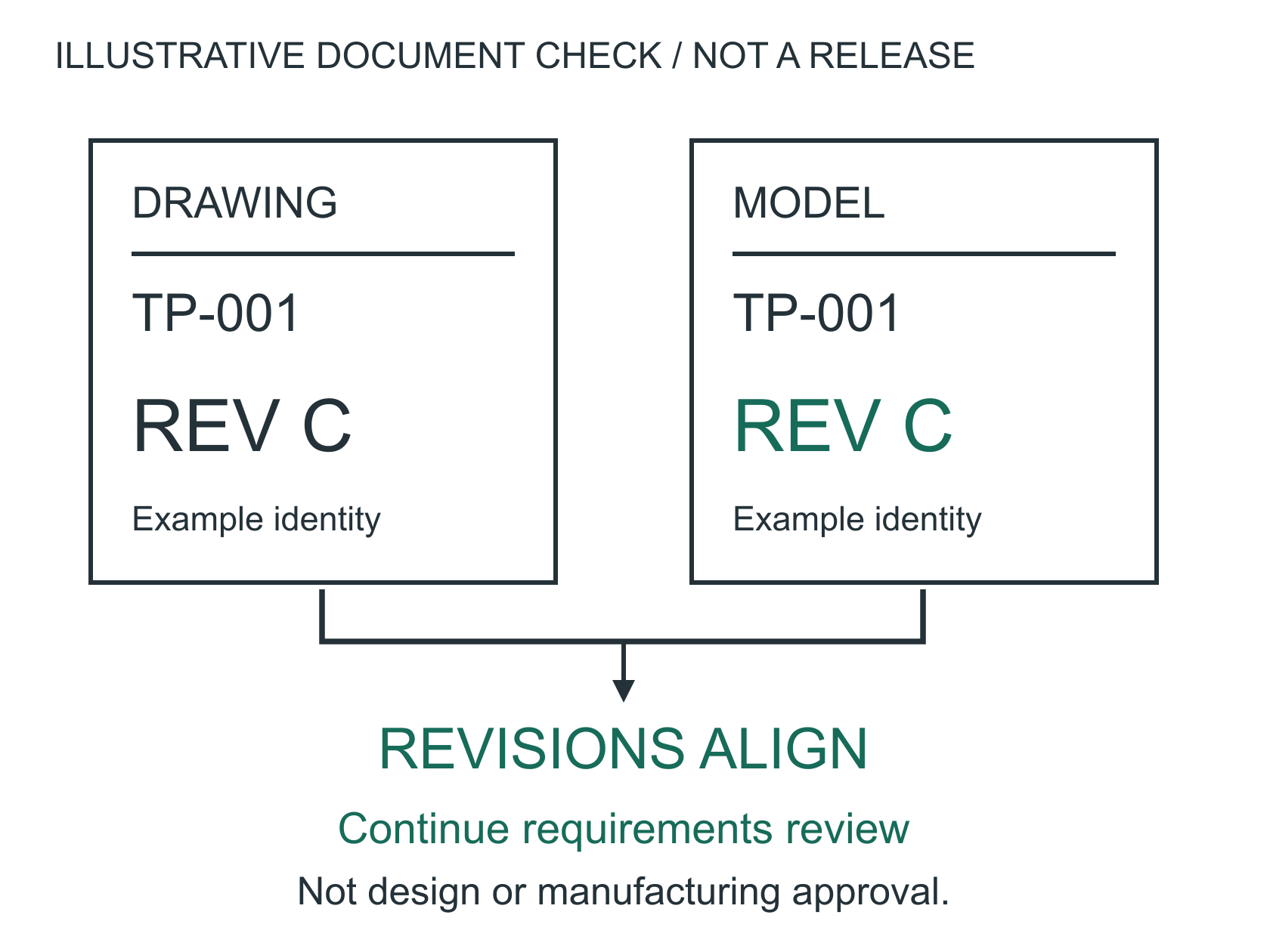
Part number, revision, material, finish, and general tolerances in the title block keep everything organized and prevent miscommunication.

Send a 3D Model If You Have One

A STEP file paired with a PDF drawing is the gold standard. The 3D model speeds up programming; the drawing defines tolerances and inspection criteria.

DFM Quick Reference

Feature Guideline Why It Matters
Internal corner radius ≥ 1/3 pocket depth Allows larger, faster tools
Wall thickness (aluminum) ≥ 0.040", prefer 0.060"+ Prevents deflection and chatter
Wall thickness (steel) ≥ 0.060", prefer 0.080"+ Steel walls resist deflection better
Hole depth ≤ 4x diameter (standard) Beyond 4x requires peck drilling
Thread engagement 1.5-2x bolt diameter Full strength without wasted depth
Height-to-thickness ratio ≤ 4:1 (easy), 4-8:1 (careful) Tall thin walls vibrate and deflect
Standard tolerance ±0.005" Tighter only where function requires
Text/engraving depth 0.010" - 0.020" Legible without excessive tool wear

Continue learning

Materials Guide Tolerances & GD&T Our Capabilities
Need DFM feedback on your design? Send Us Your Drawing
Call Now Get a Quote