Engineering · Tolerances
Tolerances & cost.
Tolerance choices affect process planning and inspection. The tiers below are qualitative examples, not cost multipliers or demonstrated process capability.
Tolerance planning
Requirements drive the process plan.
Added cost depends on the feature, material, setup, quantity and inspection method. Tolerance alone cannot predict price or the required machine.

Gauge blocks & micrometer
Tier numbers are ordinal labels, not prices or effort ratios. Review each functional feature and its manufacturing and inspection plan.
Achievable per process
Process planning examples.
The example ranges below are not measured capability distributions or job-specific acceptance limits. Feature size, material, geometry, fixturing, temperature and measurement uncertainty must be reviewed. Honing and lapping are coordinated through specialty partners.
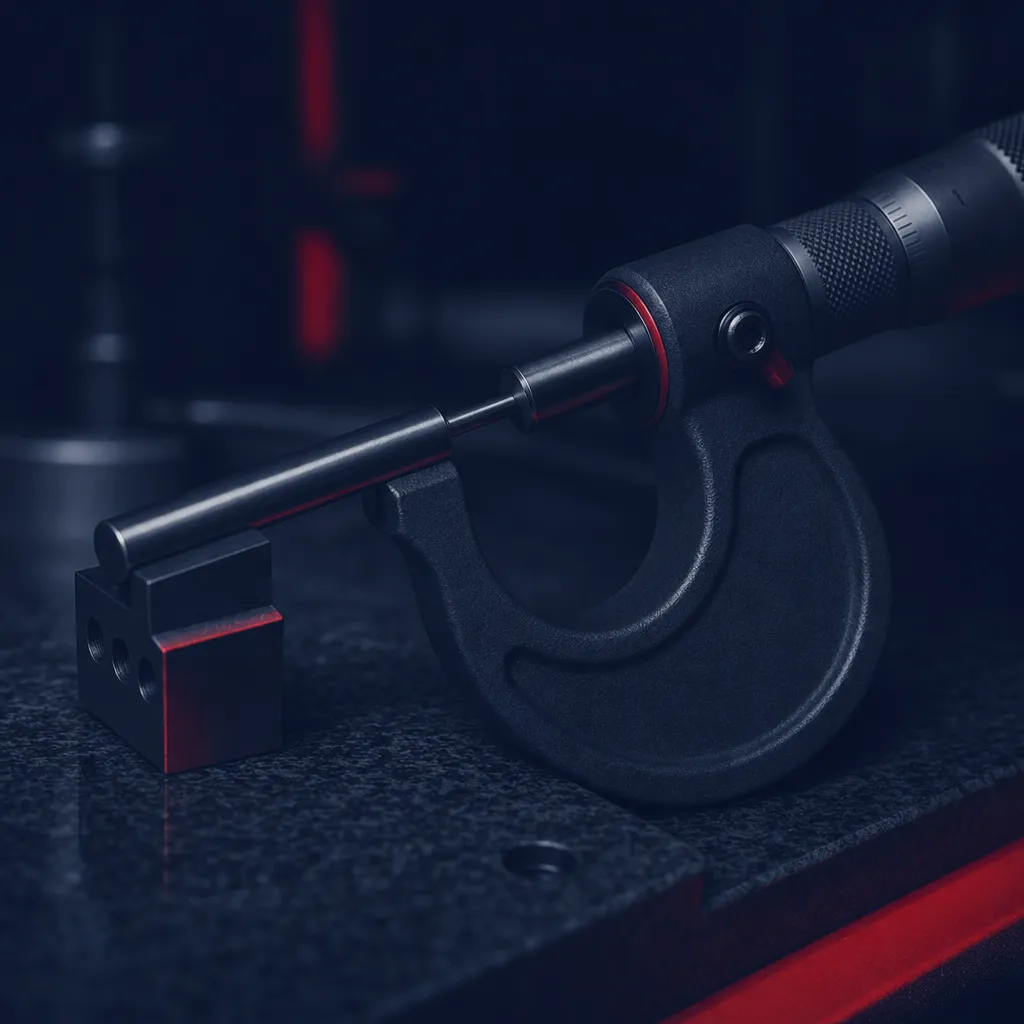
Micrometer verification on a turned pin
| Process | Standard | Tight | Best | Notes | Holds 0.001″? |
|---|---|---|---|---|---|
| 3-axis CNC mill | 0.001″ | 0.0005″ | 0.0002″ | Standard endmill operations | — |
| 5-axis CNC mill | 0.001″ | 0.0005″ | 0.0002″ | Can reduce setup transfers; does not eliminate all stack-up | — |
| CNC lathe | 0.001″ | 0.0005″ | 0.0002″ | Ground bar stock + finish pass | — |
| Swiss-type lathe | 0.001″ | 0.0005″ | 0.0001″ | Ideal for small precision parts | — |
| Wire EDM | 0.001″ | 0.0002″ | 0.00008″ | True near-net contour, no tool deflection | — |
| Surface grinding | 0.0005″ | 0.0002″ | 0.0001″ | Flat surfaces, parallel faces | — |
| Specialty operations — coordinated with outside partners (not in-house) | |||||
| Honing | 0.0005″ | 0.0001″ | 0.00005″ | Bores, primarily for cylindricity | Partner |
| Lapping | 0.0001″ | 0.00005″ | 0.00001″ | Optical / mating surfaces; per-part | Partner |
For large dimensions (over ~12″), absolute tolerances tighten relative to size — coefficient of thermal expansion alone can move a 12″ aluminum part by 0.001″ across a 4 °C temp swing. Account for this in inspection planning and CMM environment control.
ISO 2768 quick reference
General tolerances when you don’t spec one.
ISO 2768 defines four general-tolerance classes — fine (f), medium (m), coarse (c), very coarse (v). The class is invoked once at the bottom of the drawing and applies to every dimension without an explicit tolerance.
| Nominal length | Fine (f) | Medium (m) | Coarse (c) | Very coarse (v) |
|---|---|---|---|---|
| 0.5 – 3 mm | ±0.05 | ±0.1 | ±0.2 | — |
| over 3 – 6 mm | ±0.05 | ±0.1 | ±0.3 | ±0.5 |
| over 6 – 30 mm | ±0.1 | ±0.2 | ±0.5 | ±1.0 |
| over 30 – 120 mm | ±0.15 | ±0.3 | ±0.8 | ±1.5 |
| over 120 – 400 mm | ±0.2 | ±0.5 | ±1.2 | ±2.5 |
| over 400 – 1000 mm | ±0.3 | ±0.8 | ±2.0 | ±4.0 |
Values in millimeters. ISO 2768-1 covers general linear and angular tolerances. ISO 2768-2:1989 was withdrawn and replaced by ISO 22081:2021; class K is not a drop-in class in the replacement. The drawing and specified revision govern legacy mK requirements.
GD&T basics
Geometric callouts that pay for themselves.
Plus/minus tolerances on individual dimensions don’t fully describe how a part should fit and function. GD&T (geometric dimensioning and tolerancing per ASME Y14.5) lets you communicate intent — and often allows looser linear tolerances without sacrificing fit.
Symbol key — six common Y14.5 callouts · full 14-symbol reference
Flatness
How flat a surface must be, independent of its dimension. Used on mating faces, gasket surfaces.
Cylindricity
Round AND straight along the axis. Used on bearing journals, hydraulic bores.
Position
Where a feature sits relative to datums. The most common GD&T callout — replaces messy ± stackups.
Profile
Allowed deviation of a surface from its theoretical shape. Used for complex contours and faces.
Runout
Combined deviation of a feature as it rotates about a datum. Used on shafts, rotating parts.
Parallelism
How parallel one feature is to a datum. Often substitutes for tight ± distance dimensions.
For aerospace and medical drawings, full GD&T is usually mandatory. For commercial work, well-placed position and flatness callouts on functional features are usually enough — and let everything else loosen to ISO 2768-m.
Inspection
When to require First Article Inspection.
First Article Inspection (FAI) per AS9102 documents that the manufactured part meets every drawing requirement before production starts. It catches process problems early and gives you a defensible record. FAI is appropriate when:
- First production run of any new part (always)
- Any change to drawing, material, or process
- Returning to a part after a long pause (>2 years typical)
- Aerospace, medical, defense work — usually required by contract
Specify applicable AS9102 forms and first-article inspection requirements at quoting so scope and documentation can be confirmed.
Keep exploring
Related tools & references
What each tightening step actually adds to part cost.
Worst-case and RSS analysis across a dimension chain.
ISO 286 hole/shaft fits for mating features.
When geometric controls beat plus/minus dimensions.
The finish side of the same drawing callouts.
Catch tolerance choices that drive cost before release.
Need help calling out tolerances?
Tell us about your part and we'll get back to you promptly. Aerospace, medical, defense, and semiconductor production work welcome.Email CAD models and drawings to sales@digitalmachine.com, including ITAR, EAR, CUI and AS9100 work. Keep controlled technical data out of web forms.
First articles through full production runs